Introduction
When we build a computer network, one of the first practical questions is very simple: how should all the devices be connected? Computers, switches, routers, and cables cannot be placed randomly. The way they are physically arranged affects performance, cost, scalability, troubleshooting, and overall reliability.
That physical arrangement is called physical topology. In other words, physical topology describes the real layout of a network: which device connects to which, where the cables run, and how the network is built on the ground.
It is important to separate this from logical topology. Physical topology tells us how devices are connected, while logical topology tells us how data moves between them. In many cases the two are related, but they are not always identical.
Why Physical Topology Matters
A good network topology is not just about neat cabling. It directly affects how stable and manageable the network will be when more users, more devices, and more traffic are added.
Physical topology matters because it influences:
network performance
fault tolerance
redundancy
scalability
cabling cost
ease of troubleshooting
overall network design
A poor layout can create bottlenecks or even a single point of failure, where one device or one link failing can disrupt communication for many users. A better layout can make the network easier to expand and much easier to maintain.
Common Types of Physical Topology
In network architecture, the most commonly discussed physical topologies are:
star topology
ring topology
mesh topology
bus topology
tree topology
hybrid topology
Each one solves a different problem, and each comes with trade-offs.
Star Topology
In a star topology, every end device connects to one central device. In modern LANs, that central device is usually a switch. So if ten computers are part of the network, each of them gets its own direct cable to the switch.
This is the most common physical topology in present-day Ethernet networks because it is simple, clean, and practical. If one device or one cable fails, the rest of the network usually continues to work normally.
Why star topology is so widely used:
easy to install and manage
simple to add new devices
faults are easier to isolate
works naturally with switched Ethernet
commonly used in home, office, and school LANs
Main limitation:
the central switch becomes a critical dependency
if the switch fails, many connected devices lose access
more cabling is needed because every device needs a separate link
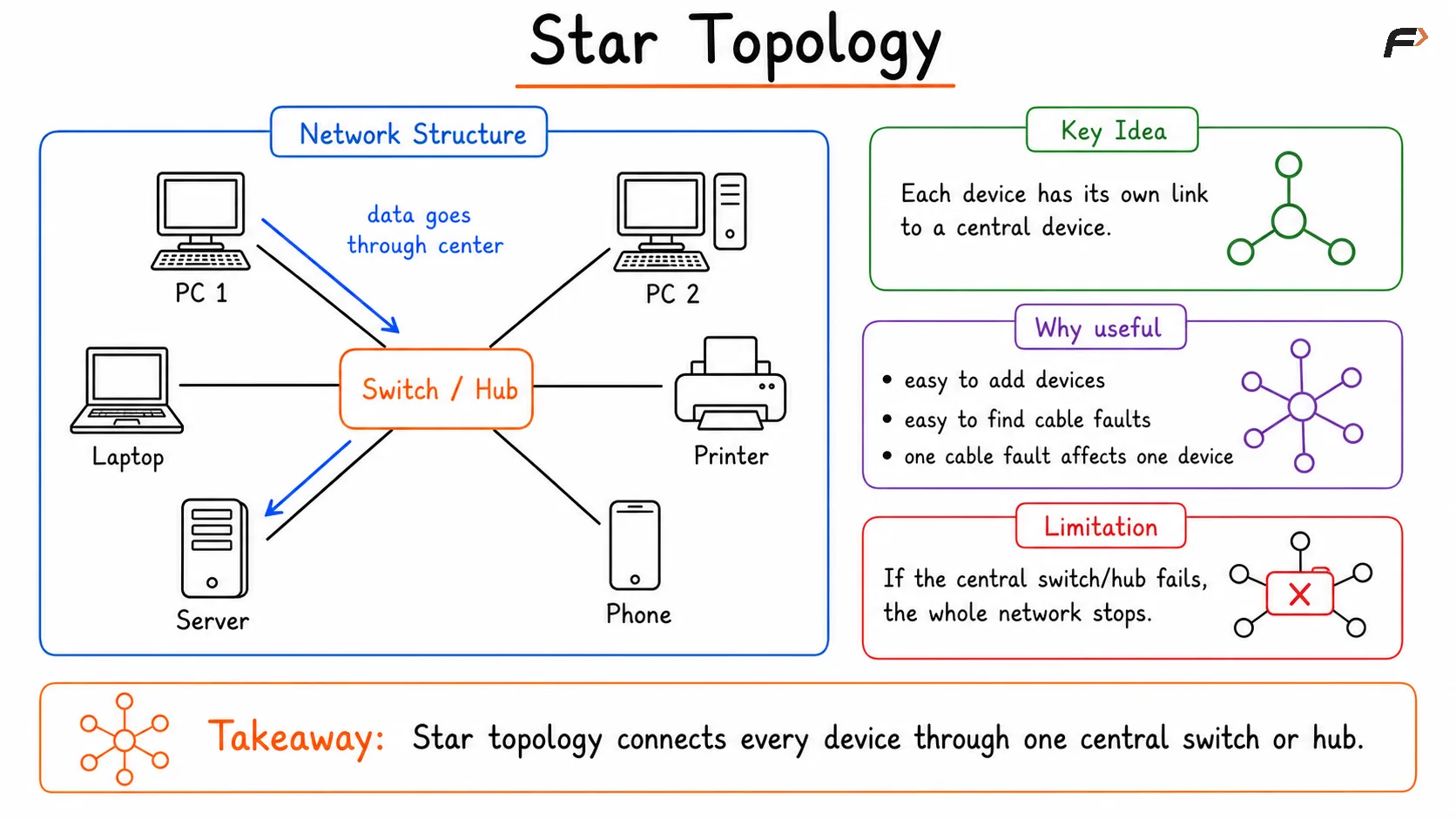
Star topology diagram showing multiple devices connected to a central switch or hub, where all communication passes through the central device, making the network easy to manage, expand, and troubleshoot.
Ring Topology
In a ring topology, each device is connected to two neighboring devices, forming a loop. Data moves from one node to the next around the ring until it reaches the destination.
This design is useful for understanding how structured communication can happen in a network. Older systems used ring-based ideas to create predictable communication, and some modern backbone or industrial environments still use ring-style designs for resilience.
Key characteristics of ring topology:
devices form a closed loop
data may move in one direction or both directions
communication can be orderly and predictable
useful where controlled access is important
Challenges:
one break in the ring can affect communication
management is harder than a simple star network
delay can increase because traffic may pass through multiple nodes
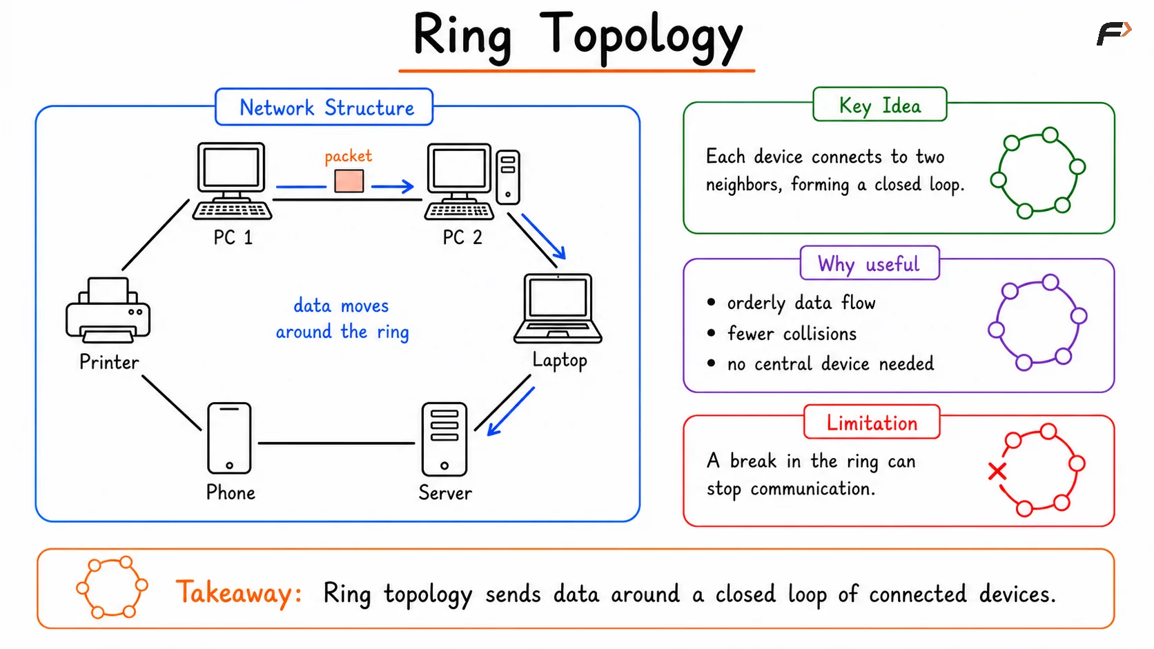
Ring topology diagram showing devices connected in a closed loop, where data travels from one device to the next around the ring until it reaches the destination.
Mesh Topology
In a mesh topology, devices are connected through multiple paths. In a full mesh, every device connects directly to every other device. In a partial mesh, only some devices have multiple direct links.
The biggest advantage of mesh topology is redundancy. If one path fails, traffic can take another route. That is why mesh ideas are important in networks where high availability and fault tolerance matter.
Why mesh topology is valuable:
strong fault tolerance
multiple communication paths
high reliability
better resilience during failures
Why it is not used everywhere:
expensive cabling and hardware
more complex configuration
difficult to scale as the number of devices grows
As the network grows, the number of required links grows very quickly. That is why full mesh is powerful, but rarely practical for large everyday networks.
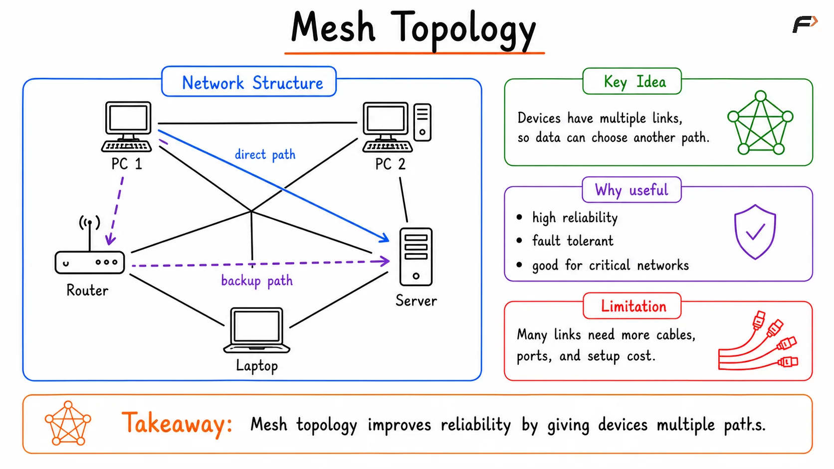
Mesh topology diagram showing devices interconnected through multiple communication links, allowing data to travel across different paths for high reliability, fault tolerance, and continuous network connectivity.
Bus Topology
In a bus topology, all devices share a single common cable called the backbone cable. Every device listens to the same shared communication line.
This topology was important in older Ethernet designs because it used less cabling. But it also had clear weaknesses. If the backbone cable failed, the whole network could be affected.
Advantages of bus topology:
simple physical design
less cabling in small setups
lower cost in early networks
Disadvantages of bus topology:
the backbone is a single point of failure
performance drops as traffic grows
troubleshooting becomes difficult
not suitable for modern large networks
Today, pure bus topology is mostly of historical importance, especially when compared with switch-based star topology.
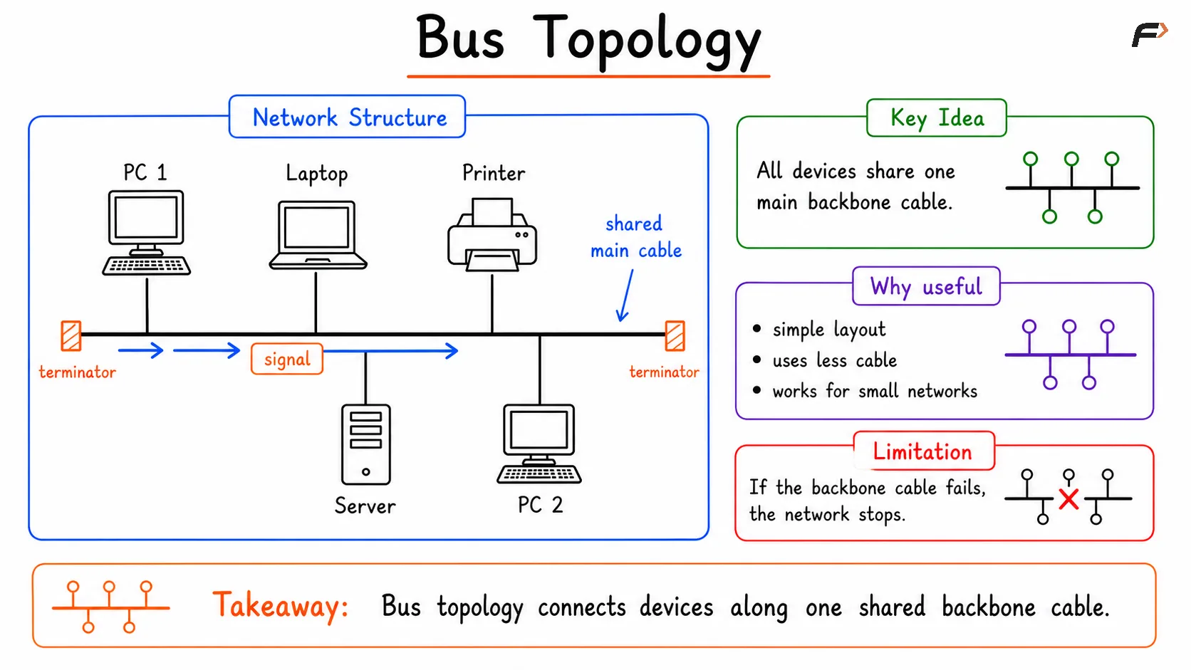
Bus topology diagram showing all devices connected to a single shared backbone cable, where data travels along the main cable and terminators at both ends prevent signal reflection.
Tree Topology
A tree topology is a hierarchical structure. You can think of it as multiple star networks connected across levels. One part of the network branches into another, which then branches further to reach end devices.
This topology is common in larger organizations because a single switch is often not enough. As a network grows across rooms, floors, departments, or buildings, a layered structure becomes more practical.
Why tree topology is useful:
supports scalability
provides a structured network layout
helps organize traffic
works well in enterprise networks and campus networks
Its trade-offs include:
more planning is required
upper-layer devices become critical
failure at a higher level can affect a larger section of the network
In real-world network design, tree topology is often seen in structured office and enterprise environments.
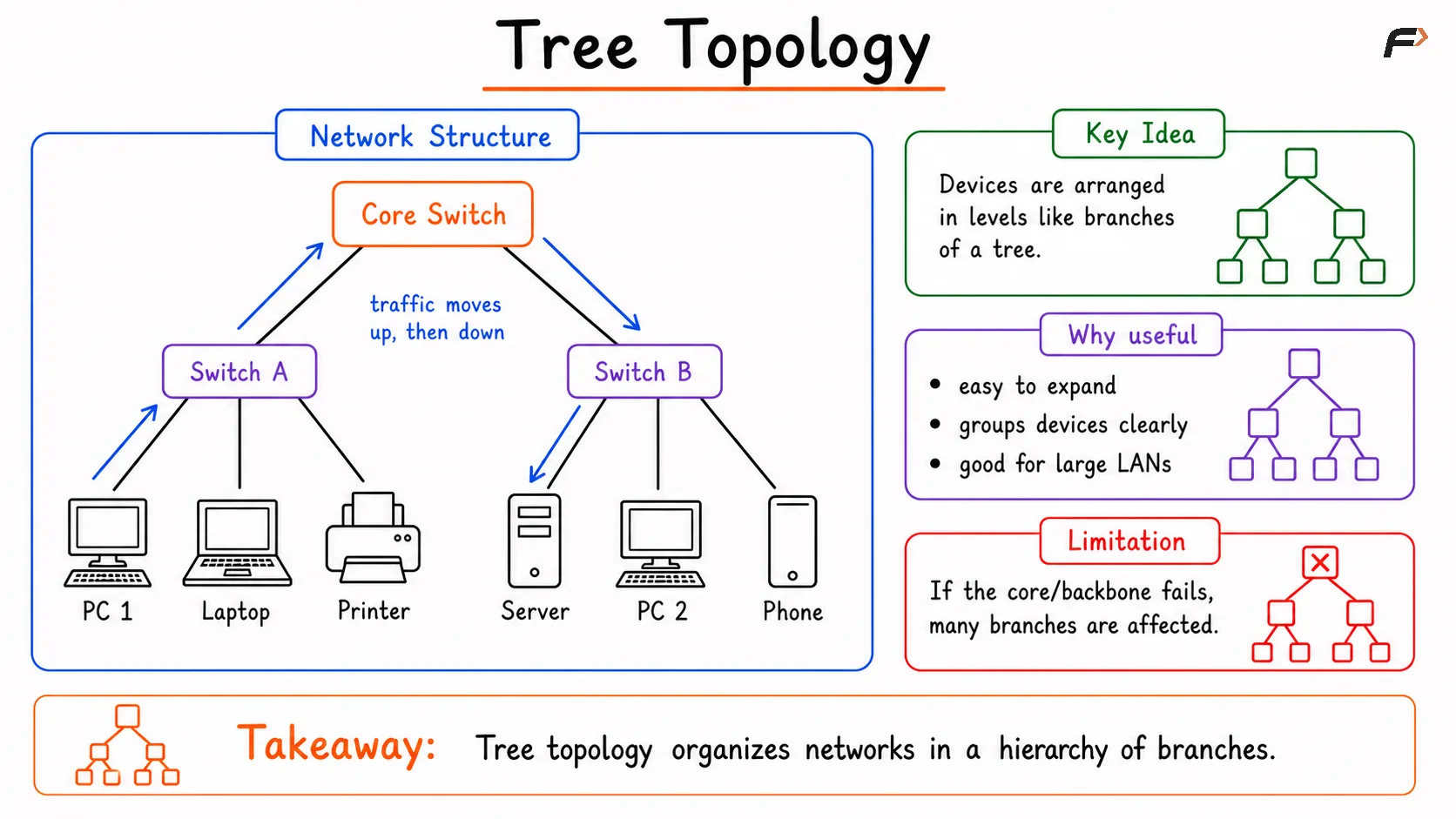
Tree topology diagram showing a hierarchical network structure, where multiple star networks are connected through a central backbone, enabling organized communication and easy network expansion.
Hybrid Topology
A hybrid topology combines two or more topologies in the same network. Real networks often do not follow one textbook pattern from end to end, so hybrid topology is very common in practice.
For example, an organization may use star topology inside each department, while the larger network between departments may follow a tree-like structure. That combination becomes a hybrid design.
Why hybrid topology is common:
flexible for real network requirements
combines strengths of different topologies
supports custom network architecture
useful in large and evolving environments
The downside is that hybrid networks are usually more complex to design, document, and maintain.
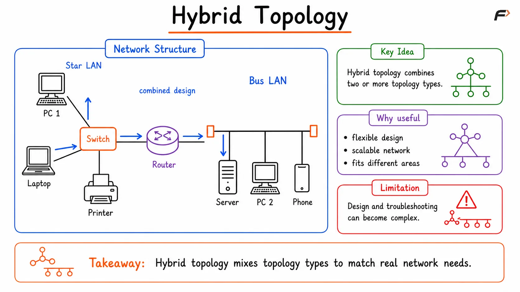
Hybrid topology diagram combining two or more network topologies, such as star, bus, or ring, to create a flexible and scalable network that meets different communication and reliability requirements.
Physical Topology and Modern Networks
In modern LAN design, star topology is the most common local arrangement because Ethernet switches make it efficient and easy to manage. At a larger scale, however, networks often grow into tree or hybrid structures.
That is why physical topology is not just a theory topic. It helps explain why office networks, campus networks, data center layouts, and backbone links are built the way they are. Once you understand topology, it becomes much easier to understand network performance, redundancy, and design choices.
Summary
Physical topology is the actual layout of devices, cables, and links in a computer network. It answers a practical question: how is the network physically built?
Different topologies serve different needs. Star topology is simple and popular, mesh topology provides redundancy, bus topology is historically important, ring topology offers structured communication, tree topology supports growth, and hybrid topology reflects how real networks are usually designed. Understanding these topologies gives a strong foundation for learning LAN design, Ethernet switching, fault tolerance, and modern network architecture.
Be the first to add a comment.