Introduction
The OSI Model is a conceptual framework used to understand how network communication works. It divides the complete communication process into seven layers, where each layer has a specific responsibility.
Instead of treating networking as one large complicated process, the OSI Model breaks it into smaller parts. This makes it easier to understand how data moves from an application on one device to an application on another device.
Why the OSI Model Is Needed
Computer networks involve many different tasks. Data must be created, formatted, secured, divided, addressed, routed, framed, converted into signals, transmitted, received, and reconstructed.
If all these tasks were handled as one single block, networking would become difficult to design, troubleshoot, and explain. The OSI Model solves this by separating responsibilities into layers.
The OSI Model helps with:-
Modularity: Each layer focuses on a specific networking responsibility.
Troubleshooting: Network problems can be identified layer by layer.
Standardization: Different vendors and technologies can follow common communication ideas.
Learning clarity: Concepts like IP addresses, MAC addresses, ports, routing, switching, and protocols become easier to place.
Interoperability: Systems can communicate even if different hardware or software is used underneath.
The Seven Layers of OSI Model
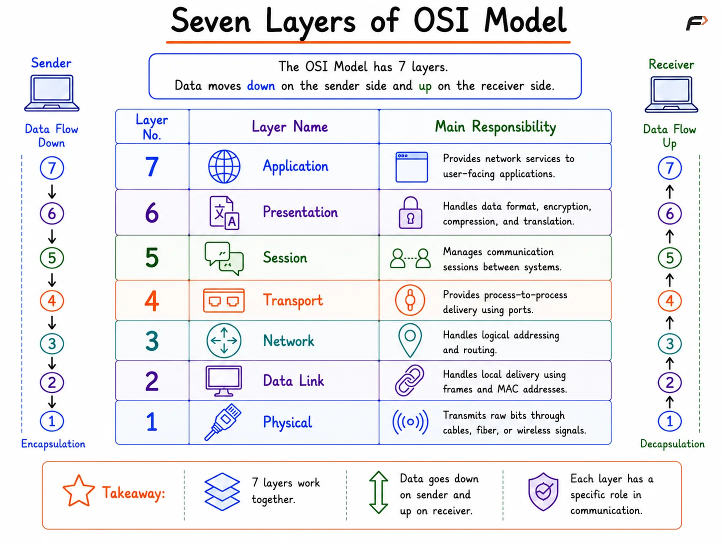
The OSI Model has seven layers. They are usually numbered from bottom to top, starting with the Physical Layer and ending with the Application Layer.
Seven Layers of OSI Model
Data moves down these layers on the sender side and moves up these layers on the receiver side.
Layer 1: Physical Layer
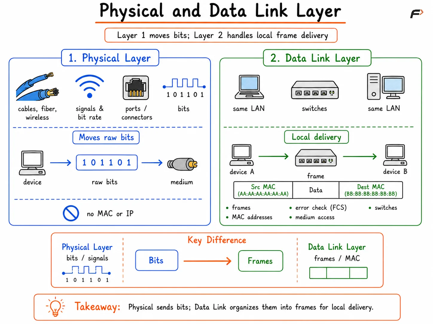
The Physical Layer deals with the actual transmission of raw bits across a physical medium. It is concerned with signals, cables, connectors, radio waves, electrical pulses, optical signals, and transmission speed.
This layer does not understand IP addresses, MAC addresses, ports, or applications. It only moves bits from one point to another.
Common examples include:
Cables: Ethernet cables, coaxial cables, and fiber optic cables.
Wireless signals: Wi-Fi, Bluetooth, and radio transmission.
Hardware interfaces: Network cards, connectors, and physical ports.
Signal properties: Voltage levels, light pulses, frequency, and bit rate.
The unit of data at this layer is generally considered bits.
Physical and Data Link Layer
Layer 2: Data Link Layer
The Data Link Layer is responsible for communication within the same local network. It takes raw bits from the Physical Layer and organizes them into frames.
This layer uses MAC addresses to deliver frames between devices on the same LAN. Switches mainly operate at this layer.
Important responsibilities include:
Framing: Converts raw data into frames for local network delivery.
MAC addressing: Uses source and destination MAC addresses.
Error detection: Detects frame-level errors using mechanisms like FCS.
Medium access control: Decides how devices access the shared medium.
Local delivery: Moves frames between devices in the same network segment.
Examples include Ethernet, Wi-Fi, MAC addresses, VLANs, and switches.
Layer 3: Network Layer
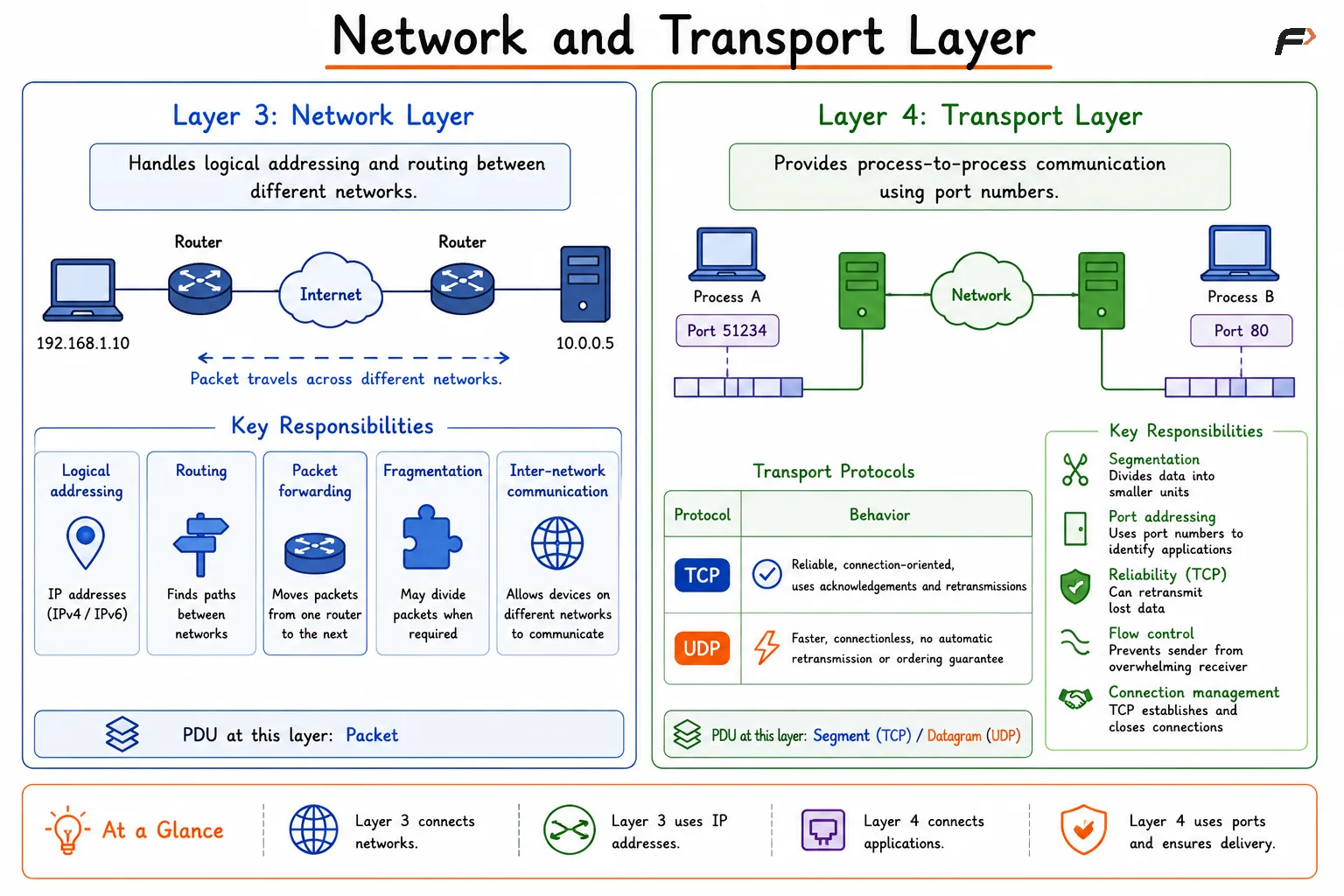
The Network Layer is responsible for logical addressing and routing between different networks. It uses IP addresses to identify source and destination devices across interconnected networks.
Routers operate mainly at this layer. When data needs to travel from one network to another, Layer 3 decides the path.
Key responsibilities include:
Logical addressing: Uses IP addresses such as IPv4 and IPv6.
Routing: Finds paths between different networks.
Packet forwarding: Moves packets from one router to the next.
Fragmentation: May divide packets when required by network limits.
Inter-network communication: Allows devices on different networks to communicate.
The unit of data at this layer is called a packet.
Network and Transport Layer
Layer 4: Transport Layer
The Transport Layer provides process-to-process communication. It ensures that data reaches the correct application process using port numbers.
This layer is where TCP and UDP operate. TCP provides reliable communication, while UDP provides faster, connectionless communication without built-in reliability.
Protocol | Behavior |
|---|---|
TCP | Reliable, connection-oriented, uses acknowledgements and retransmissions |
UDP | Faster, connectionless, no automatic retransmission or ordering guarantee |
Transport Layer responsibilities include:
Segmentation: Divides data into smaller units.
Port addressing: Uses port numbers to identify applications.
Reliability: TCP can retransmit lost data.
Flow control: Prevents sender from overwhelming receiver.
Connection management: TCP establishes and closes connections.
The unit of data at this layer is commonly called a segment for TCP and a datagram for UDP.
Layer 5: Session Layer
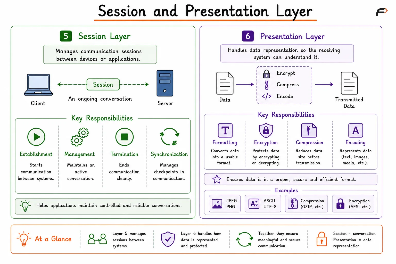
The Session Layer manages communication sessions between devices or applications. A session represents an ongoing conversation between two systems.
This layer is responsible for starting, maintaining, and ending sessions. In modern internet systems, these responsibilities are often handled by protocols and applications rather than a visibly separate session layer.
Session Layer responsibilities include:
Session establishment: Starts communication between systems.
Session management: Maintains an active conversation.
Session termination: Ends communication cleanly.
Synchronization: Helps manage checkpoints in communication where required.
The Session Layer is important conceptually because many real applications need controlled conversations, authentication state, and connection continuity.
Session and Presentation Layer
Layer 6: Presentation Layer
The Presentation Layer handles data representation. It ensures that data is in a format the receiving system can understand.
It is also associated with encryption, decryption, compression, and data translation. For example, when data is encrypted before being sent or decoded after being received, that idea fits naturally into the Presentation Layer.
Common responsibilities include:
Data formatting: Converts data into a usable format.
Encryption and decryption: Protects data confidentiality.
Compression: Reduces data size before transmission.
Encoding: Represents data in formats such as text, images, or media.
Examples include formats and mechanisms like JPEG, PNG, ASCII, UTF-8, compression, and encryption concepts.
Layer 7: Application Layer
The Application Layer is the topmost layer of the OSI Model. It provides network services used by applications.
This does not mean the application itself is the layer. Instead, it means the protocols and services that applications use for network communication belong here.
Common examples include:
HTTP/HTTPS: Web browsing and web APIs.
DNS: Domain name resolution.
FTP: File transfer.
SMTP: Email sending.
IMAP/POP3: Email retrieval.
DHCP: Automatic IP configuration.
When a browser opens a website, it uses Application Layer protocols like DNS and HTTP/HTTPS to communicate over the network.
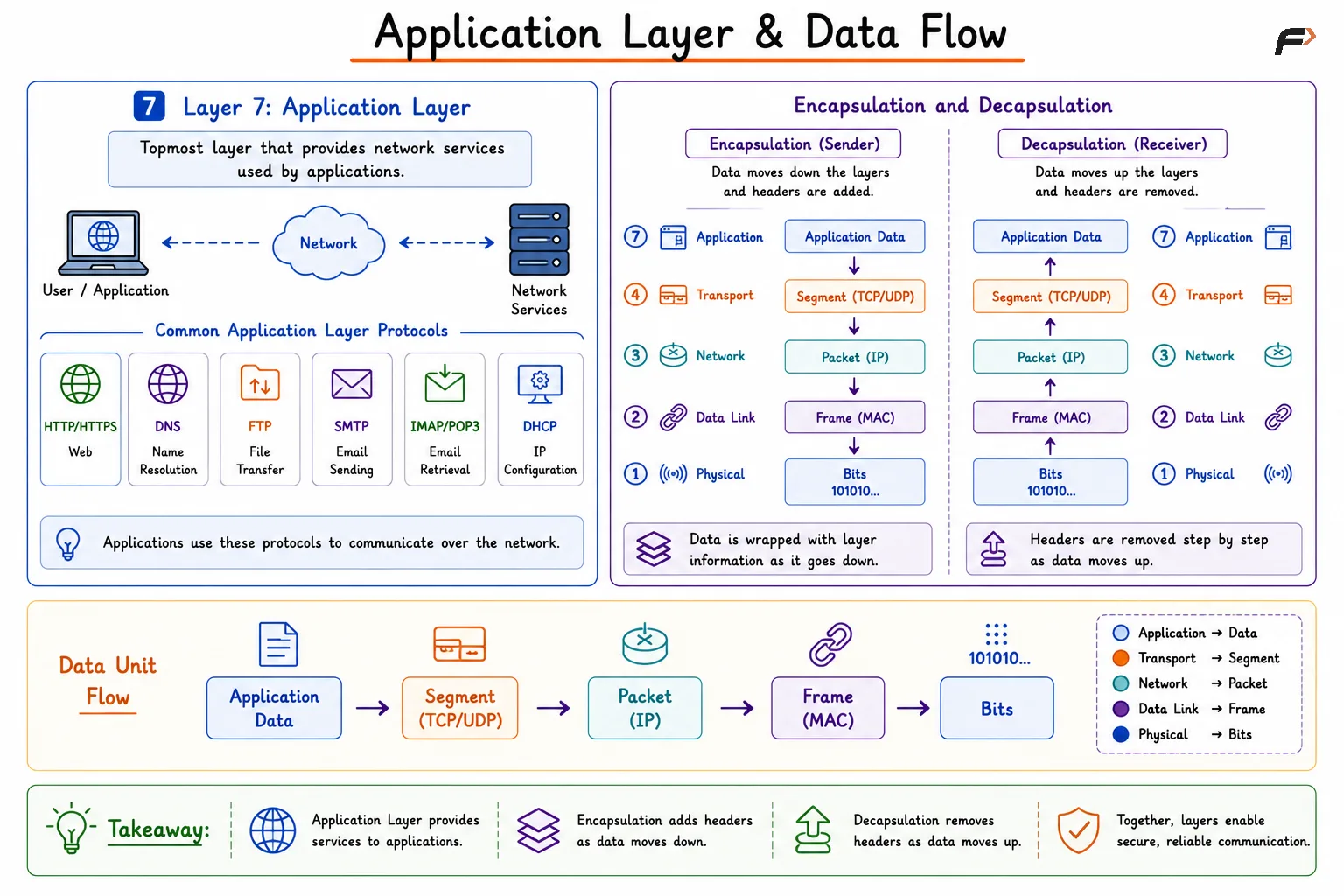
Application Layer and Data Flow
Encapsulation and Decapsulation
Encapsulation is the process of adding layer-specific information as data moves down the OSI layers on the sender side.
For example, application data is passed down to the Transport Layer, where TCP or UDP information is added. Then the Network Layer adds IP information. The Data Link Layer adds frame information. Finally, the Physical Layer sends bits through the medium.
A simple flow is: Application Data => Segment => Packet => Frame => Bits
Decapsulation happens on the receiver side. The receiver removes layer information step by step as data moves upward until the application receives the original data.
OSI Model Data Units
Each layer works with a different form of data. These are called Protocol Data Units, or PDUs.
OSI Layer | Data Unit |
|---|---|
Application | Data |
Presentation | Data |
Session | Data |
Transport | Segment or Datagram |
Network | Packet |
Data Link | Frame |
Physical | Bits |
This mapping is useful because networking terms often depend on the layer being discussed. A switch forwards frames, a router forwards packets, and the physical medium carries bits.
OSI Model vs TCP/IP Model
The OSI Model is mainly a reference model used to understand networking clearly. The TCP/IP Model is the practical model used by the internet.
OSI Model | TCP/IP Model |
|---|---|
Application, Presentation, Session | Application |
Transport | Transport |
Network | Internet |
Data Link, Physical | Network Access |
The TCP/IP Model combines some OSI layers because real-world internet protocols do not always separate responsibilities exactly the same way. Still, the OSI Model remains very useful for learning, troubleshooting, and explaining network behavior.
Summary
The OSI Model is a seven-layer framework that explains how network communication works from physical signals to application-level services. Each layer has a specific responsibility, such as transmitting bits, framing data, routing packets, managing ports, handling sessions, formatting data, or supporting application protocols.
The model helps organize important networking concepts like MAC addresses, IP addresses, TCP, UDP, routing, switching, encapsulation, protocols, and troubleshooting. Although real internet communication commonly follows the TCP/IP Model, the OSI Model remains one of the clearest ways to understand how data moves across a network.
Be the first to add a comment.