Introduction
A MAC address and an Ethernet frame are two core ideas in local network communication. Devices inside a LAN do not send raw IP packets directly over the wire. At the Data Link Layer, communication happens through Ethernet frames, and those frames use MAC addresses to identify the sender and receiver on the current network link.
This is why both topics are closely connected. A MAC address tells the frame where to go on the local network, and the Ethernet frame provides the structure that carries that information from one device to the next.
What a MAC Address Is
A MAC address, or Media Access Control address, is the local hardware address used at the Data Link Layer. It identifies a network interface on the current local network and helps switches deliver frames to the correct device.
A MAC address is usually 48 bits, or 6 bytes, long and is commonly written in hexadecimal form, such as:
00:1A:2B:3C:4D:5E
In local communication, the MAC address is used for hop-to-hop delivery. That means it helps move a frame across the current link, not across the entire internet.
MAC Address vs IP Address
MAC addresses and IP addresses are both used in networking, but they serve different purposes.
Aspect | MAC Address | IP Address |
|---|---|---|
Layer | Data Link Layer | Network Layer |
Purpose | Local delivery on the current link | End-to-end delivery across networks |
Scope | Hop-to-hop | End-to-end |
Used by | Switches and Ethernet communication | Routers and IP communication |
Changes during the path | Can change at every hop | Usually remains the same from source to destination |
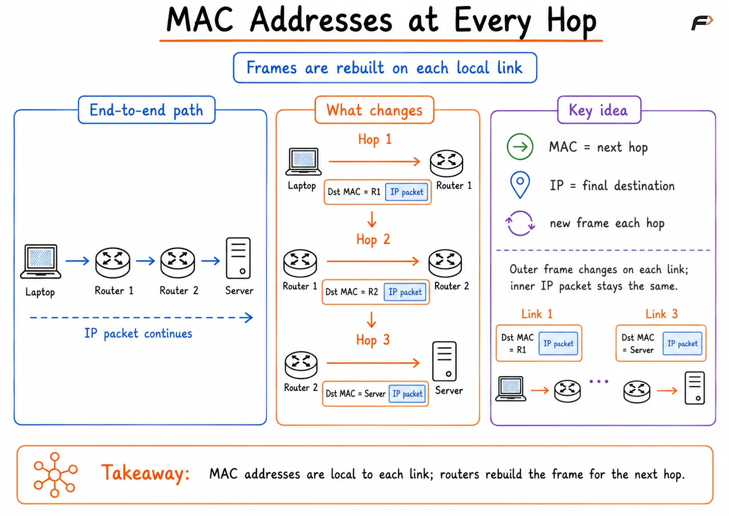
This difference is one of the most important ideas in networking. The destination IP address usually stays constant from sender to final receiver, but the destination MAC address is rewritten at each hop because each new frame is addressed to the next device on the path.
Why MAC Addresses Change at Every Hop
When a device sends traffic to a remote network, it already knows the destination IP address of the final target. But it cannot send an Ethernet frame directly to that distant machine unless the machine is on the same local link.
Instead, the frame is first sent to the next hop, which is often the default gateway.
For example, if the path is:
Laptop => Router 1 => Router 2 => Server
then the forwarding works like this:
First frame: Destination MAC is Router 1.
Next frame: Router 1 removes the old frame, keeps the IP packet, and creates a new frame for Router 2.
Final frame: Router 2 creates another new frame whose destination MAC is the server's MAC address.
The IP packet continues toward the same final destination, but the Ethernet frame is rebuilt at each hop for the next local link.
MAC Addresses
ARP and MAC Address Resolution
A device cannot send a frame unless it knows the destination MAC address for the current link. In IPv4 networks, this mapping is done using ARP, or Address Resolution Protocol.
If a host wants to send traffic and does not know the MAC address of the destination device or default gateway, it uses ARP to discover it. Once the MAC address is learned, the host can build the Ethernet frame correctly.
For IPv6 networks, the similar function is handled by NDP, or Neighbor Discovery Protocol.
What an Ethernet Frame Is
An Ethernet frame is the basic unit of communication in an Ethernet LAN. It carries data across the local link and includes the addressing information needed for Layer 2 delivery.
At higher layers, a device may have an IP packet that contains:
source IP address
destination IP address
upper-layer data or payload
When that packet is prepared for transmission over Ethernet, the Data Link Layer adds local delivery information such as source MAC address, destination MAC address, and error-checking fields. The result is an Ethernet frame.
Purpose of an Ethernet Frame
An Ethernet frame does more than just carry data. It gives structure to communication on the local network.
Its main purposes are:
Encapsulation: Wraps upper-layer data for local transmission.
Local addressing: Identifies the sender and receiver on the current link.
Organized delivery: Allows switches and NICs to process frames correctly.
Error detection: Helps detect whether the frame was damaged in transit.
Without Ethernet frames, devices in a LAN would have no standard way to package and exchange local network data.
Main Fields of an Ethernet Frame
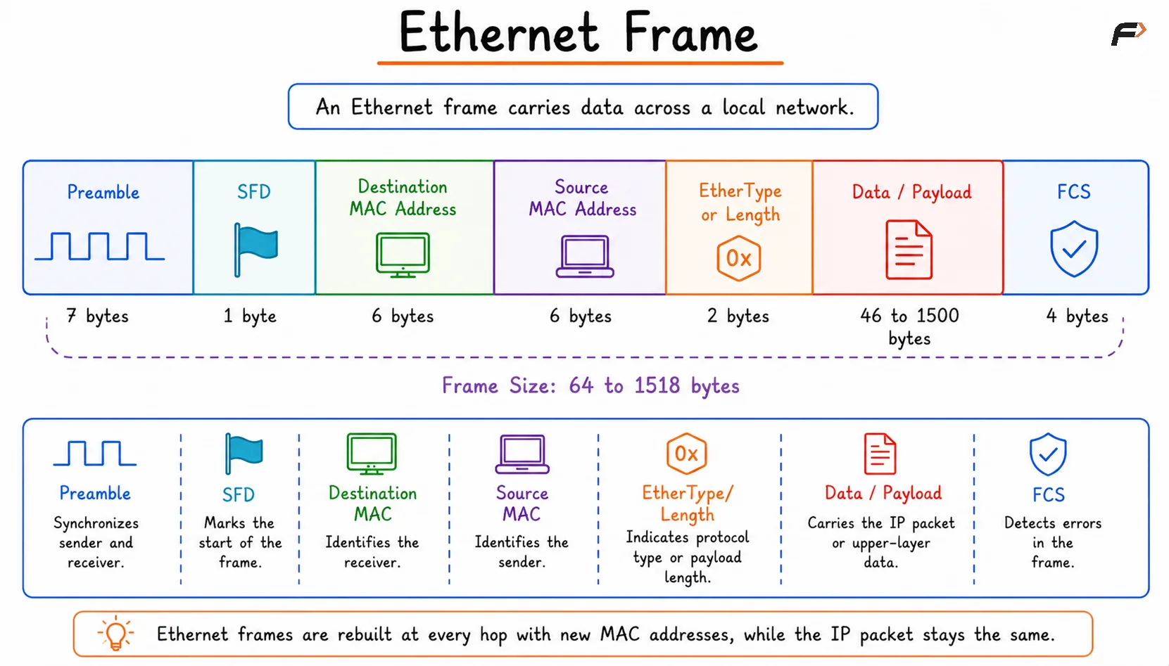
An Ethernet frame contains multiple fields, each with a specific role.
Field | Size | Purpose |
|---|---|---|
Preamble | 7 bytes | Helps synchronize sender and receiver before transmission |
Start Frame Delimiter (SFD) | 1 byte | Marks the actual start of the frame |
Destination MAC Address | 6 bytes | Identifies which device should receive the frame |
Source MAC Address | 6 bytes | Identifies which device sent the frame |
EtherType or Length | 2 bytes | Indicates the protocol carried or payload length |
Data or Payload | 46 to 1500 bytes | Contains the IP packet or upper-layer data |
Frame Check Sequence (FCS) | 4 bytes | Used for error detection |
This structure is what allows Ethernet communication to remain consistent across devices and networks.
Ethernet Frame
CRC and FCS in Ethernet Frames
Ethernet includes error detection so that damaged frames can be identified and rejected. The mechanism commonly used is CRC, or Cyclic Redundancy Check.
CRC is the algorithm used to calculate an error-detection value. That result is placed into the FCS, or Frame Check Sequence, field of the Ethernet frame.
At the receiving side:
Frame received: The receiver reads the incoming frame.
CRC recalculated: The receiver computes its own CRC value.
Comparison performed: The computed value is compared with the received FCS.
Decision made: If the values match, the frame is accepted. If not, the frame is treated as corrupted and discarded.
This helps Ethernet detect transmission errors at Layer 2.
Why Padding Is Needed
Ethernet frames must follow a minimum size requirement. A standard Ethernet frame must be at least 64 bytes long, which means the payload must be at least 46 bytes.
If the actual data is smaller than that, the frame is padded with extra bits to meet the minimum size.
Small payload: Actual data is less than 46 bytes.
Padding added: Extra bytes are inserted.
Receiver ignores padding: These bytes are not treated as useful application data.
Padding exists to satisfy Ethernet frame size requirements and support reliable transmission behavior.
How MAC Address and Ethernet Frame Work Together
A MAC address and an Ethernet frame are not separate ideas in practice. The MAC addresses are part of the Ethernet frame itself.
The frame carries:
Source MAC address: Which local device sent the frame
Destination MAC address: Which local device should receive the frame
Payload: The actual upper-layer data being carried
This is what makes local switching possible. A switch reads the destination MAC address in the Ethernet frame and forwards the frame toward the correct port.
Summary
A MAC address is the Layer 2 hardware address used for local, hop-to-hop delivery on a network link, while an Ethernet frame is the structured unit of data that carries MAC addressing information across a LAN. MAC addresses help devices identify the next local receiver, and Ethernet frames package that information along with payload and error-detection fields.
Together, they form the foundation of local network communication. Understanding MAC addresses, ARP, Ethernet frame fields, FCS, CRC, and padding makes it much easier to understand how switching works inside an Ethernet network.
Be the first to add a comment.