Introduction
In any computer network, devices must be connected so that they can communicate with one another. As networks grow larger, simply connecting devices is not enough. We also need to understand how devices are arranged, how data moves between them, and how one physical network can be divided into multiple logical networks.
This topic introduces three important ideas:
device arrangement
data movement
logical division of networks
Together, these form the foundation of how Local Area Networks (LANs) are designed and managed.
Why Do We Need Network Topologies?
When a network depends too much on a single device or communication path, failure of that component can disrupt the entire network. This is called a Single Point of Failure (SPOF).
To improve reliability, networks often add redundancy through backup devices or alternate paths. Once a network contains multiple devices and paths, it becomes important to decide how those devices should be arranged.
This arrangement is described using network topology.
Two Important Views of a Network
When studying a network, we usually answer two questions:
How are the devices connected?
How does data move between them?
These lead to two related but different concepts:
Physical Topology
Logical Topology
Physical Topology
Physical topology describes the actual structure of the network. It shows how devices, cables, switches, and links are connected in the real world.
It answers questions such as:
which devices are connected together
how the cables are arranged
what the network physically looks like
For example, if multiple computers are connected to a central switch, that is part of the physical topology.
Logical Topology
Logical topology describes how communication happens in the network. It focuses on the path and behavior of data rather than the physical layout.
It answers questions such as:
which devices can communicate directly
how traffic flows
what rules control communication
This means that even if two devices are physically connected to the same switch, they may still belong to different logical networks.
So, physical connectivity and logical communication are not always the same.
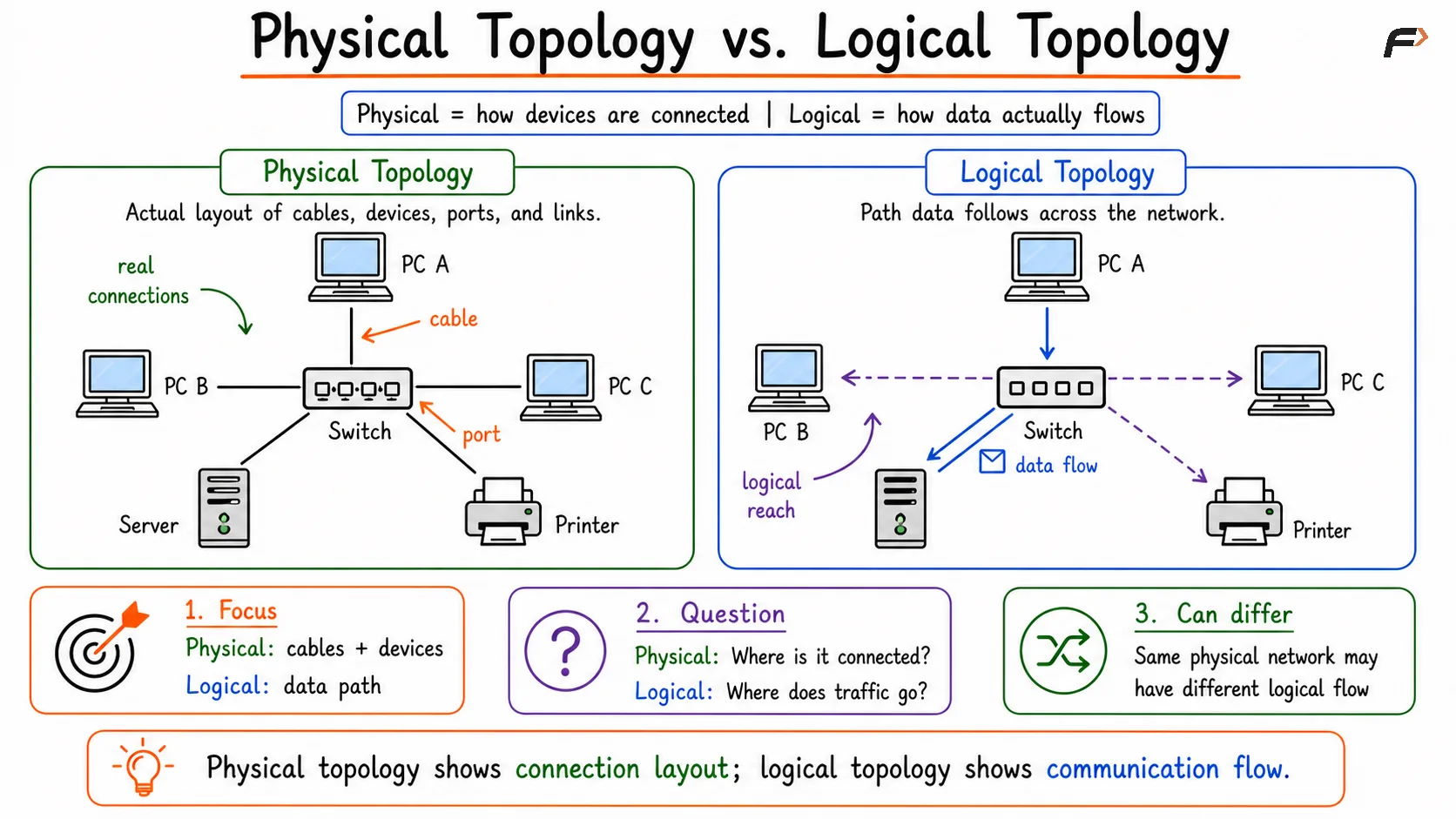
Comparison diagram showing physical topology as the actual layout of devices, cables, ports, and connections, while logical topology illustrates the path that data follows through the network between connected devices.
Understanding VLANs
A VLAN (Virtual Local Area Network) allows a single physical network to be divided into multiple logical networks.
This means devices connected to the same switch can still be separated into different groups for communication purposes.
For example, in an office network:
Engineering may be in VLAN 10
Sales may be in VLAN 20
Management may be in VLAN 30
Even though all devices may be connected to the same physical switch, they are logically separated into different virtual networks.
VLAN Communication
Devices in the same VLAN can communicate directly with one another. However, devices in different VLANs are logically isolated by default.
For example:
PC1 is in VLAN 10
PC2 is in VLAN 20
PC3 is in VLAN 30
Even if all three systems are connected to the same switch, they will not automatically communicate with one another because they belong to different logical networks.
Communication Between VLANs
If devices in different VLANs need to communicate, a routing device is required.
This can be:
a Router
a Layer 3 Switch
This device forwards traffic between VLANs and enables inter-VLAN communication.
Summary
The main idea is that the physical arrangement of devices and the logical flow of communication are not always the same.
A group of devices may share the same physical infrastructure but still be divided into separate logical networks using VLANs. In such cases, communication between those VLANs requires routing.
This distinction is essential for understanding modern LAN design.
Be the first to add a comment.