Introduction
During data transmission, noise, interference, hardware failures, or signal degradation can corrupt data. To ensure that the receiver can identify transmission errors, networks use various error detection techniques. These techniques add extra information to the transmitted data, allowing the receiver to verify whether the received data matches the original data.
Three commonly used error detection methods are Parity Check, Checksum, and Cyclic Redundancy Check (CRC). Each technique provides a different level of error-detection capability and computational complexity.
Parity Check
Parity Check is one of the simplest error detection techniques. It works by adding an additional bit, called the parity bit, to the data before transmission. The parity bit is chosen so that the total number of 1s in the transmitted data becomes either even (even parity) or odd (odd parity).
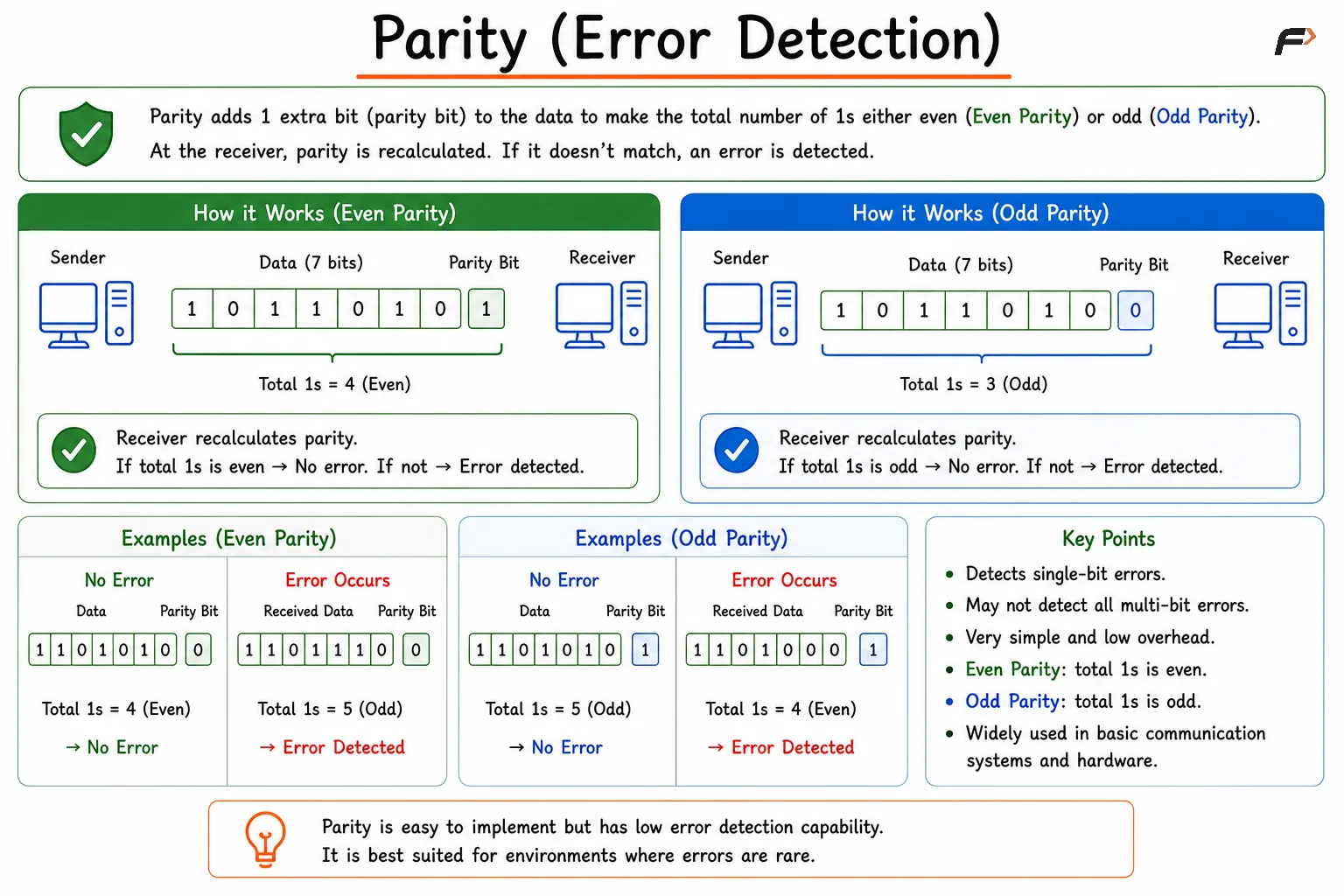
Parity error detection is explained using even and odd parity, showing how a parity bit is added, verified by the receiver, and used to detect transmission errors through step-by-step examples.
Example
Assume we want to transmit: 1011001
The data contains four 1s, which is already an even count.
Even Parity => Add parity bit = 0
Transmitted Data => 10110010
If the receiver receives: 10100010
The number of 1s becomes three (odd), violating the even parity rule. The receiver can therefore detect that an error has occurred during transmission.
Limitations of Parity Check
Parity checking can only reliably detect an odd number of bit errors. If an even number of bits change during transmission, the parity may still appear correct and the error can go undetected.
For example:
Original Data : 10110010
Corrupted Data: 10010011
Although two bits changed, the total number of 1s remains even, causing the error to go unnoticed. Because of this limitation, parity checking is simple and inexpensive but provides relatively weak error detection.
Checksum
Checksum is an error detection method that calculates a numerical value from the data being transmitted. This calculated value, known as the checksum, is sent along with the data. The receiver performs the same calculation and compares the result with the received checksum. If the values differ, an error is detected.
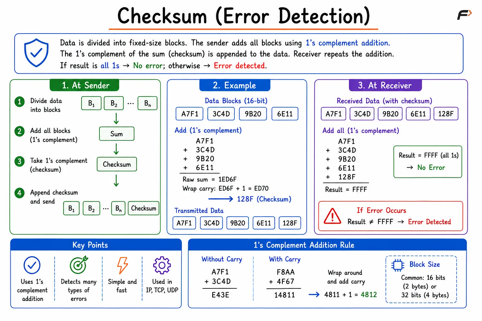
Checksum error detection is illustrated by dividing data into fixed-size blocks, generating a checksum using 1's complement addition, and verifying it at the receiver to detect transmission errors through a worked example.
Example
Suppose the sender wants to transmit the following 8-bit values:
10010011
00110101
Adding them: 11001000
The checksum is generated from this result and transmitted with the data.
At the receiver side, the same calculation is performed. If the computed checksum does not match the received checksum, the receiver concludes that the data has been corrupted during transmission.
Checksums are commonly used in protocols such as IP, TCP, UDP, and various file-transfer systems because they provide better error detection than simple parity bits while remaining computationally efficient.
Cyclic Redundancy Check (CRC)
CRC is one of the most powerful and widely used error detection techniques in computer networks. Instead of counting bits or adding values, CRC treats data as a binary polynomial and performs a mathematical division using a predefined generator polynomial.
The remainder produced by this division is called the CRC value and is appended to the transmitted data. The receiver performs the same division operation and checks whether the remainder is zero. A non-zero remainder indicates that an error has occurred.
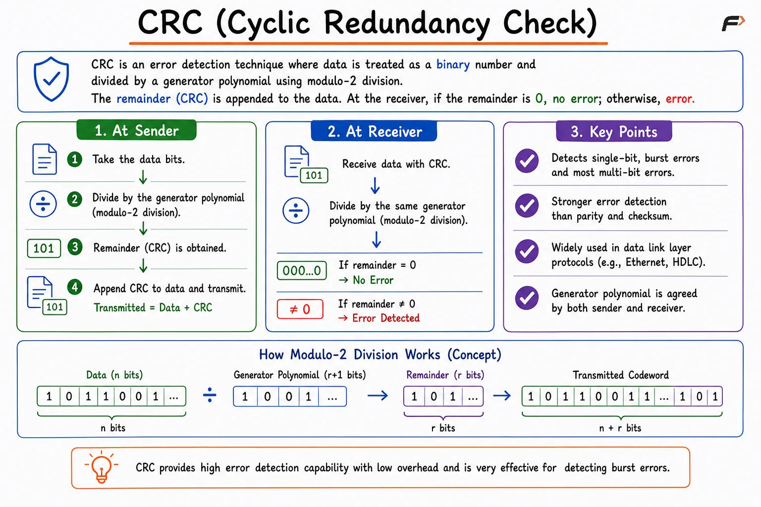
CRC error detection is explained through sender and receiver workflows, showing modulo-2 division with a generator polynomial, appending the CRC remainder to transmitted data, and checking for errors by verifying whether the received remainder is zero.
Example
Assume:
Data = 110101
Generator = 1011
The sender performs CRC division and obtains a remainder. CRC Remainder = 111
The transmitted frame becomes: 110101111
When the receiver receives this frame, it performs the same CRC division using the generator polynomial. If the remainder is zero, the data is assumed to be correct. Otherwise, a transmission error is detected.
Although the mathematical process is more complex than parity checks or checksums, CRC provides significantly stronger error detection and can identify many common transmission errors with high accuracy.
Summary: Parity vs Checksum vs CRC
Technique | Basic Idea | Error Detection Strength | Complexity |
|---|---|---|---|
Parity Check | Add a parity bit based on the number of 1s. | Low | Very Low |
Checksum | Calculate and transmit a numerical checksum value. | Medium | Low |
CRC | Use polynomial division and transmit the remainder. | High | Moderate |
Be the first to add a comment.